
Sailboat Electrical Systems
This page is dedicated to resources regarding sailboat electrical systems. With the growth of LiFePO4 phosphate battery systems over the past decade, sailboat electrical systems can be built, fairly cost effectively, that can bring a level of comfort to sailing that previously couldn’t be imagined. This page is under construction.
First some notes about safety: American Mainsail, LLC and its authors are not licensed marine electricians. Marine electrical projects can carry risk of electric shock or fire. Consult and always follow manufacturer’s manuals and instructions. Consult a qualified marine electrician before undertaking a marine electrical project. The Many qualified marine electricians are available that can offer their expertise while you design and build your system, some are even available to offer advice over Facetime/Skype/the phone. The purpose of this article is to get you pointed in the right direction and asking the right questions when thinking about your marine electrical system. It reflects advice based on the author’s experience. This article is not a comprehensive set of instructions on how to wire your specific system and does not represent the advice of a qualified, marine electrician.
Resources
Victron “Wiring Unlimited” Book
Marine Electrical Example Systems/Schematics (from Blue Sea Systems):
https://www.bluesea.com/systems
Many different examples available, including simpl(er) center console type systems and larger trawler/sailboat type systems.
Fully detailed Victron Energy electrical system schematic (with 3000 watt inverter-charger, shore power, and generator)
ABYC Excerpts (from Blue Sea Systems)
Ever wonder what that “IP” rating means on electrical products? Here’s an explanation:
“UL” Information
Lithium Electrical Systems in Sailboats (Battle Born Batteries Blog): https://battlebornbatteries.com/using-lithium-batteries-in-sailboat-electrical-systems/
Battle Born Academy: https://battlebornbatteries.com/learn/academy/
Example Systems and Bundles
Battle Born/Victron sailboat bundles: https://battlebornbatteries.com/shop/applications/sailboat/
https://explorist.life/category/blog/plans-and-diagrams/
Fantastic wiring diagrams for off-grid RV electrical setups featuring Victron Energy components. While these setups are geared towards RVs, they are very similar to off-grid marine/sailboat installations. When using Victron Energy components, the extra concerns that marine systems need to take into account are: using ignition-protected fusing components, using marine-grade wiring, and installing galvanic isolators in the shore power system.
Wiring

Wires in an electric circuit… not all that different from a pipe that carries water from a raised tank!
I like to think of designing a circuit like designing a network of pipes that distributes water to a city through an elevated water tank (bear with me). The pressure in the pipes (due to the height of the tank) is like the voltage in the wires, V (measured in volts). The speed of the flow of water through the pipes is like the current, I (measured in amps, or milliamps (thousandths of an amp)).
If you were designing a piping system, what are some things you’d think about?
We’d probably install gate valves located at specific locations to be able to turn the flow on and off (these are switches). We’d want to make sure that the gate valves can control the pressure and flow (voltage and current) that we’re expecting in the pipes (wires).
We’d want to size the pipes (size the wires) appropriately to be able to handle the amount of flow (current) we’re expecting and can deliver enough water (voltage and current) to the customer. The pressure/voltage analogy kind of breaks down here. Pressure would be important in a pipe, but the wire we’re using for boat circuits can generally handle any voltages we’ll be using in our system. Current is the most important thing we’re concerned about when sizing wires.
We’d want to make sure that automatic safety valves (fuses) are installed close to the water tank (the batteries) so that we can shut the wire down as close to the tank (battery) as possible should there be a leak (a short) in the pipe (wire) somewhere down the line to avoid flooding the town (burning the boat down). A safety valve located too far from the tank wouldn’t do us any good if the leak is located between the tank and the safety valve. We also want to make sure that the safety valves (fuse interrupt capacity) are sized large enough to interrupt the out of control flow should there be a leak (short)
Unless the distribution system was very simple (serving just a couples homes), we’d want a way to bring the water all in one place to control its distribution (a bus bar, or for even more complex systems a circuit breaker panel) to gather the water and distribute it to the right place.
We’d want to make sure that all of the plumbing is installed in a solid way that won’t leak in the future, or create obstructions that will hamper the flow and give unreliable service. We want to use tools designed for installing marine wiring and use good materials that are designed and tested for the tough environment that the wires/components will live in. Using the wrong tools and materials can result in corrosion, voltage drop, heat, failures, and fire risk.
Lastly, we want to make sure that the pipes are well supported and installed in safe places. We want our wires to be supported at least every 18”, and protected from sharp objects and chafe. We may want to protect our wire in wire loom.
DC Grounding
Grounding can be a confusing and debated (surprise!) subject between sailors. Some argue to tie all grounds together (see Nigel Calder’s book we link to in our Sailing Resources page, including metallic thru-hulls. Other’s argue to ground each circuit according to its purpose. See the following article.
This article by electrical engineer Stan Honey, originally published in Practical Sailor, is one of the best I’ve come across that describes grounding systems.
Also see Stan’s website: http://honeynav.com/
Choosing Wire Size
When wiring any circuit, it’s important to choose the correct wire size (usually measured in AWG - higher AWG wire is smaller). Picking the right size wire ensures that your circuit will operate safely and efficiently. Use the tools below to choose the correct size wire for your project.
Blue Sea Systems - Choosing Wire Size
This is a great resource for familiarizing yourself with the fundamentals of sizing wires for marine electrical installations. Once you’re familiar with the fundamentals, you can use the calculator I’ve linked below to quickly calculate wire sizes for your project.
Blue Sea Systems - Circuit Wizard (works for 12, 24, and 32V)
Wire Sizing Calculator (works with all voltages).
Sizing the right size wire for both the solar panel side and battery side of the controller is very important for both safety and good performance. Be sure to specify copper wire. Try to keep voltage drops around 2%. Find the max. temperature specs. for the wire you intend to use to plug into the calculator. I suggest only using quality, marine-grade wiring. I suggest plugging in temperature specs. into the calculator that are well below the maximum specified temperature of the wire you’re using. Generally, plugging a 1-3% voltage drop in the wires should ensure that your wire won’t get hot, but it’s always smart to be as careful as possible when sizing wires.
Fusing/OVer-Current Protection
Fusing is extremely important when dealing with marine electrical. The essence of a fuse is to protect the wire from melting in an over-current/short situation, which can lead to fires. Since fiberglass is flammable, fires onboard a fiberglass boat can quickly spread, leading to a rapidly developing, very dangerous situation. Think of a fuse like a pressure release valve. If a wire is carrying too much current (pressure), the fuse will blow (safely), protecting the wire from melting and potentially starting a fire. Since fuses protect the wires in your circuit, fuses are sized according to the size of the wires they are in circuit with.
Resources
https://marinehowto.com/battery-banks-over-current-protection/
This page, written by Rod Collins of MarineHowTo, is an absolutely fantastic write-up about marine fusing. This writeup is great general knowledge to understand about fusing, and is particularly applicable to battery-controller side fusing
https://d2pyqm2yd3fw2i.cloudfront.net/files/resources/reference/20010.pdf
Blue Sea Systems - Sizing wiring, fuses, and fuse holders single-page procedure
Blue Sea Systems - Selecting Fuses and Fuse Holders
Blue Sea Systems Full-Scale Fuse Comparison
Shore Power
Shore power is still a vital part in any boat’s electrical system. It is often routed to a pass-thru inverter/charger, or may be wired to a charger and then directly to AC loads through circuit breakers.
30 and 50 amp RV/Marine (NEMA L5) Connections
Sail Magazine - How to Avoid Shore-power Problems - https://www.sailmagazine.com/cruising/how-to-avoid-shore-power-problems
The typical 30 amp and 50 amp marine connection (called the NEMA L5-30R for 30 amp connections) can be a fragile connection. There are many examples out there of this connection causing, or nearly causing, fires when they melt down due to arcing/high resistance. My friends and I that live aboard in the Northeast generally push their shore power inlets to max capacity with electric heat in the winter. I have noticed scorching on the hot terminal of mine, and others, 30 amp NEMA cord. Boaters generally shrug these occurrences off because they’re just so common with these connections.
Keep the terminals clean and monitor the electrical terminals for signs of scorching. Internal wiring issues may also be present in these kinds of shore power inlets. At max load, check the temperature of your shore power cord with an infrared temperature gun (Amazon Affiliate Link). The SAIL Magazine article I linked above suggests that 10°F above ambient is problematic and 20°F above ambient is an indicator that immediate action is necessary. I suspect that many of these connections are operating above these specs due to corrosion, wearing out, etc. and are a fire hazard.
Reddit user reports nearly catastrophic shore power inlet issue. Discussion shows that this is fairly common with existing 30-amp connection style.
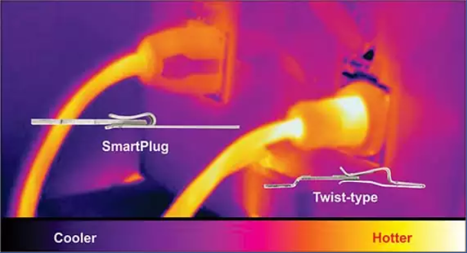
A snip from Smart Plug’s website: by providing more electrical contact area, a more robust locking mechanism, and corrosion-resistant materials and design Smart Plug decreases temperatures at the shore power inlet by lowering electrical resistance at the shore power connection. This significantly reduces the chance of electrical fires on your boat.
For safety, strongly consider updating your shore power inlet to Smart Plug (West Marine affiliate link) connections. The smart plug increases the electrical contact area of the shore power inlet connection, plugs straight in (it does not require aligning the connector or a twist-lock action to lock), uses more corrosion-resistant materials in its construction, and provides gasketed protection to its electrical connectors. Smart Plug shore power connections are a special concern for liveaboards in cold or hot environments that draw large loads through their shore power inlets and spend a significant amount of time on their boats.
30 Amp NEMA Smart Plug Conversion Kit (West Marine Affiliate Kit)
Note that the shore power cords made by Smart Plug are very expensive. However, you can retrofit your existing shore power cord with the smart plug female end in the kit, or buy the female end separately for retrofitting additional shore power cords.